A graphical digital circuit simulator that seamlessly connects to real world circuitry through Raspberry Pi GPIO pins for advanced prototyping and testing. Users can create and simulate a circuit using the logic gates and components provided. Then, they can create complex testing scenarios or prototype by connecting digital logic to their real world circuitry.
Making an SR-Latch
A Full Adder with real life input and output
This section is for compiling on a computer without GPIO functionality, to compile on to the Raspberry Pi with GPIO functionaly see Cross-compilation.
Although this code is meant to be compiled on to a Raspberry Pi, it is possible to compile an older version of the codebase on a computer. This version might have certain missing features but does have a completely functional logic gate simulator. It can be found at the branch circuits_project/tree/non-gpio. Once you have this version of the code downloaded, you will need to install Qt and Qt Creator. Then, you can open the .pro file from within Qt Creator and compile/run the program.
This section is for cross-compiling on to the Raspberry Pi, to compile on a computer see Compilation.
This code was only tested on a Raspberry Pi 4B, so even though it should work on other Raspberry Pi versions, that is the only one I can recommend. In order to cross-compile to a Raspberry Pi, you will need a computer or a virtual machine running linux. To avoid any compatibility issues, I would recommend using Linux 20.04. As there is already a comprehensive guide on how to cross-compile a Qt project to the Raspberry Pi here I will not be going over each step. Instead, you can follow that guide with one difference:
- When installing all of the dependenices onto the Raspberry Pi in the initial setup steps, also install the libgpiod library with
sudo apt-get install gpiod libgpiod-dev
- Increase customization of GPIO interfacing components & complete the Singleton setup
- Add time/tick control
- Add more components (clock, delay, LED)
- Add custom component saving and placing
- Add save file system
- Add support for analog input and ADC/DAC components
Below is a more comprehensive description of some of the more complex or significant parts of the code.
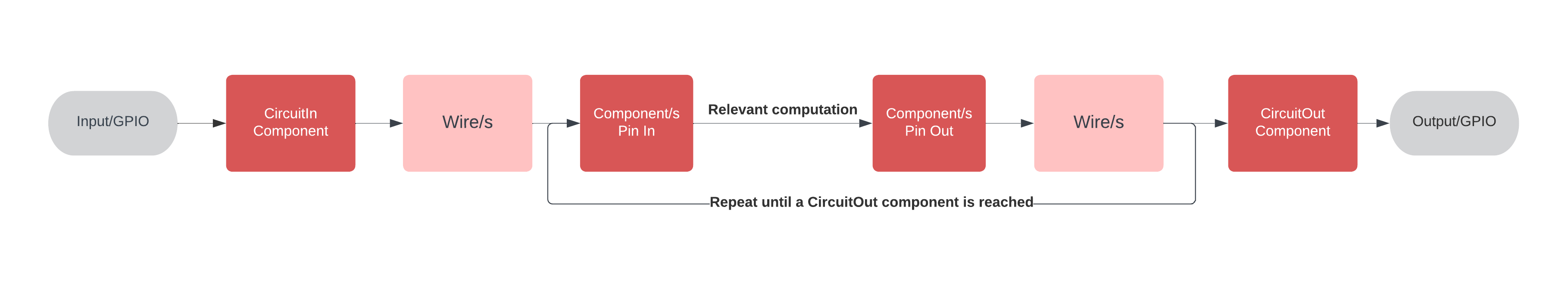
- The bit is taken from an input source and is stored as a state on an input component
- The bit is moved into each wire connected to each pin-out
- The bit is moved from each wire to the pin-in of any component they are connected to
- The component runs any necessary computation on the bit and sets it to each pin-out's state
- The bit is moved from each pin-out to any wire connected to them
- Repeat steps 3 - 5 until an output component is reached
- The bit is moved from the wire to the output component
- The bit is moved from the output component to an output source
Simultaneity is maintained throughout the circuit by enacting every step to each component before moving on to the next step. These steps are:
- Move state from the pin-in wires to each pin-in's state
- Run necessary computation on the pin-in states and set each pin-out's state
- Move state from the pin-outs to the wires connected to them
In order to allow for the creation of several components that all interface with the same GPIO pins, the CircuitIn and CircuitOut components use the Singleton design pattern. This way, the GPIO pins are connected to only once even if multiple graphical objects interact with them.
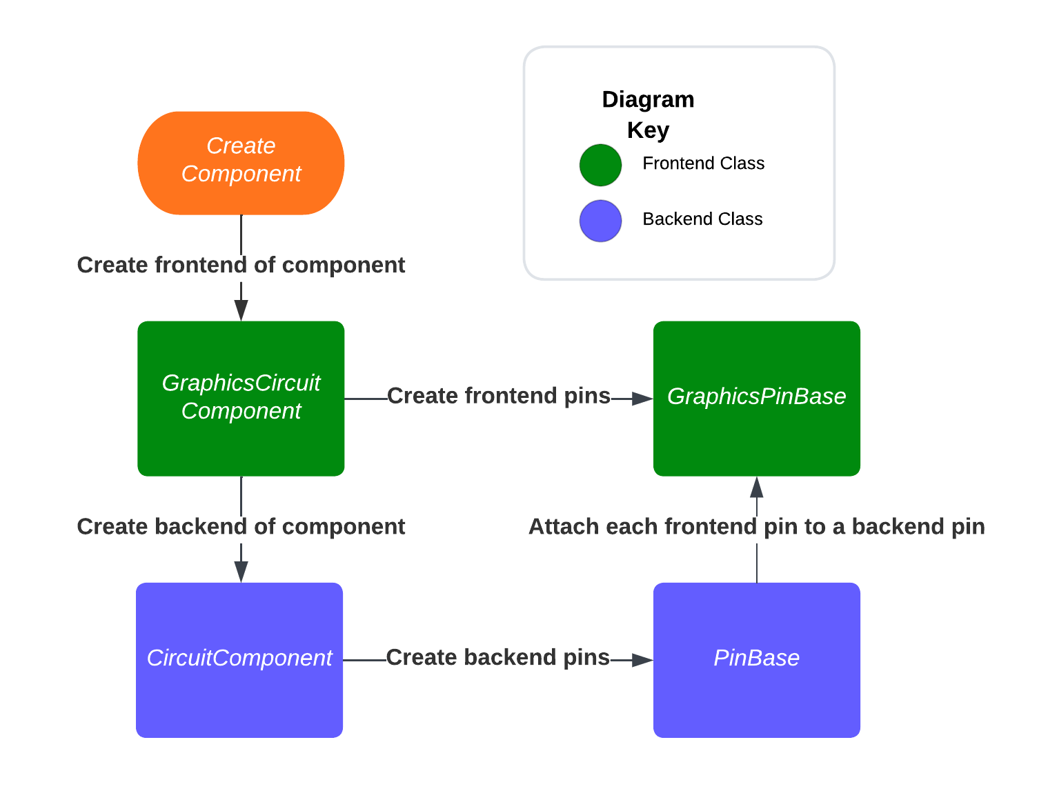
The frontend objects have a reference to them stored in the scene object. The scene object has two lists, one only for components that I maintain, and one for adding objects for the Qt framework to display on the scene. Before a frontend object is deleted, it is removed from these two lists to avoid dangling pointers. In most cases the frontend component is responsible for creating the backend component. In some more complex cases such as the creation and connection of frontend and backend pins an approach similar to the one outlined in the flowchart below is taken. This allows the backend component to be responsible for creating the backend pins while still creating a connection between the frontend and backend pins.
The frontend objects (often labeled with the prefix "graphics") all contain a pointer to their backend counterparts. The frontend components' destructors are responsible for calling delete on the backend components. Then the pointer pointing to those backend components are set to nullptr and the frontend component is destructed as well. All other objects that hold a reference to the deleted backend or frontend components (such as the pins) are also deleted in the destructor of either the frontend or backend component respectively. Through this system, most of the projects' memory management can be handled in a fairly straight forward manner.
However, there are some complications that appear due to the existence of wires. This is because both objects that the wire is connected to hold a pointer to the wire. In order to prevent wild pointers I handle the deletion of wires or the deletion of components that cause wires to be deleted as follows:
- When a wire's destructor is called through the delete keyword, the wire "disconnects" itself from any pins by removing any references of itself from those pins
- When a component's destructor is called through the delete keyword, the component calls delete on each one of it's pins, and then clears all reference to the pins. When the delete keyword is called on a pin, the pin calles the delete keyword on each one of it's wires, and then clears all reference to the wires. The destructor of wires is as outlined above.
- When both wires and components are selected to be deleted at once, I go through the selected items and delete the wires first so that the components deleting any other wires connected to them does not cause dangling pointers.
These actions that are applied to a frontend component or wire are also propogated to their backend counterparts in a similar fashion.