This project contains code that renders an image as a series of lines connecting pins around a circular frame. For more detail in the physical implementation of these pieces, see my article on Medium. The file line_generation is a Python script containing all the code required to generate your own pieces of art. The 4 sections in this document are:
- Algorithm description (which includes High level description, giving the broad strokes of how the algorithm works, and Function by function, which looks at each function and its purpose in detail)
- How to run, which gives the instructions for running the line_generation file.
- Algorithm Examples, where I describe how I've provided example pieces of code that you can try out.
- Final thoughts, in which I outline the future directions I might take this algorithm.
This is a very broad description of the algorithm. It misses a lot of finer points, so if you read anything in this next paragraph that is contradicted elsewhere, it is likely incorrect here, but has been simplified for the purpose of explainability.
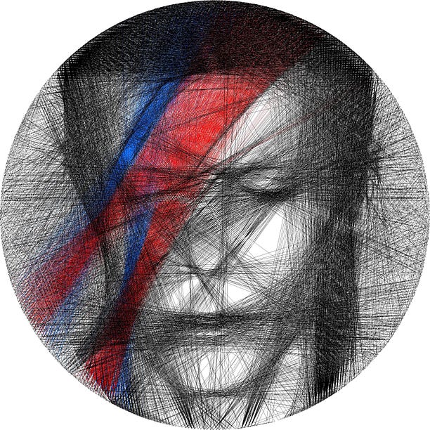
First, an image is converted into a square array of greyscale pixel values from 0 to 255, where 0 represents white, and 255 black. The coordinates for the pin positions are calculated. A number of lines are drawn between randomly chosen pairs of pins, and each line is tested by calculating how much it reduces the overall penalty (which is defined as the sum of all the absolute pixel values in the image). A line will change the penalty by reduding the value in all the pixels it goes through by a certain amount. For instance, a line through a mostly black area might change pixel values from 255 to 155, this reduces the penalty a lot. A line through a mostly white area (or an area over which many lines have already been drawn) might change pixel values from 50 to -50, this will not reduce the penalty. Once all these penalty changes have been calculated, the line which reduces the penalty the most will be chosen, the pixel values will be edited accordingly, and this process will repeat. If a randomly selected line happens to already have been drawn, the algorithm will compute the change in penalty brought about by removing it instead of adding it; this allows the algorithm to eventually reach a point of equilibrium, where it is adding lines as fast as it removes them. Once the random line selection has run a certain number of times, the algorithm terminates. For the images that use colour, I generally just run the algorithm on each colour separately, using very specific images (see the David Bowie lightning file for a perfect example of this).
The second half of the code creates a Eulerian path, which is a path around the vertices that uses each edge exactly once. For this to exist, we require 2 conditions: the the number of lines connected to each side of the pin must be the same (since every line must enter the pin on one side, and leave on the other side), and the graph must be connected (i.e. we can't have 2 separate islands of connected pins, even if those islands individually obey the previous rule). The first thing the code does is add lines so that these 2 conditions are satistfied (when I make my art, these lines go round the outside of the wheel, so they don't interfere with the image), then a path is iteratively built up using Hierholzer's algorithm.
generate_pins
- Generates the position of pins, given a particular number of pins, image size, and nail pixel size.
- Creates 2 lists of vertex coordinates (one for the anticlockwise side of the pins, one for the clockwise size), and meshes them together so that the order they appear in the final output is the order of vertices anticlockwise around the frame.
through_pixels
- Finds which pixels a line between particular pins runs through.
- Adjusted so that the number of pixels (approximately) equals the distance between the pins.
fitness
- Measures how much line improves image. improvement is difference in penalty, i.e. new penalty - old penalty (where a smaller penalty is better).
- Penalty is the sum of absolute values of positive pixels, plus absolute values of negative pixels times a lightness penalty (for more explanation, see section How to run).
- The adding parameter in fitness means that it can calculate the improvement either from adding a line, or from removing a line that is already in the image.
optimise_fitness
- Process of adding a new line is as follows:
- Generate random lines (ensuring they aren't the same line, or the same but reversed, or connecting the same pin), then find the line with the best fitness.
- Subtract this line from the image.
- Return the new image, the best line (i.e. which vertices are on either end of it), and a boolean which specifies whether a line is being added or removed.
find_lines
- Calls optimise_fitness multiple times to draw a set of lines.
- Updates the image and the list of lines with each line drawn.
- Every 10 lines drawn, prints output that describes the progress of the algorithm, including lines drawn and run time.
hms_format
- Takes a time, and converts it into hh:mm:ss. Used in find_lines function, to report alg progress.
get_penalty
- Calculates the total penalty of the image.
prepare_image
- Takes a jpeg or png image file, and converts it into an array of bytes.
- weighting=True means the image is meant to be an importance weighting (so the array returned has values between 0 and 1, where 1 means black, so high importance, and 0 means white, so low importance).
- colour=True means the image is meant to be read based on saturation instead of darkness of pixels; this is one way you can use colour in your images (although this isn't suitable for many images, I only used it for the tiger).
prepare_unif_weighting
- Generates an image with a uniform weighting, which can be used if you haven't specifically designed a weighting.
save_plot
- Saves the lines generated by the algorithm in the working directory - can then be opened with Paint, or some other standard editor.
edge
- Creates a class for edges that makes the path-finding process easier. Among the things this class allows me to do efficiently are:
- Find the pin number, the node number (these two are different, as each pin has 2 nodes, corresponding to its 2 sides) and the orientation (i.e. which pin side is being referred to) of the two vertices which are connected by the edge.
- Flip the direction of an edge (i.e. from node B to A, rather than A to B)
- Look for edges that are connected to this edge (connected in the sense that the pair of edges share the same pin number, but not the same node number, so they can be traced by thread sequentially).
extra_edges_parity_correct
- Takes in edge_list and returns the extra edges needed so that every pin has the same number of edges on either side.
- This algorithm is quite complicated, since I have put a lot of thought into how to make sure the extra edges added are the easiest to physically implement, so I will not go into detail - if people are interested, please send a message!
get_closest_pair
- Used in the extra_edges_parity_correct algorithm, to find the closest pair of vertices to match up.
extra_edges_connect_graph
- Adds extra edges so that the graph is connected.
add_connected_vertex
- Takes a set of vertices and an edge list, and adds a vertex not currently in s that can be connected (by an edge in the edge_list) to the rest of s.
- The boolean at the end says whether a new vertex was successfully added, if not then it is necessary to add a new edge.
get_adjacant_vertices
- Takes a set of vertices and its compliment, and returns a pair of vertices (in set and compliment respectively) that are a distance of 1 apart from each other.
create_cycle
- Creates a path from edges in edge_list, starting from first_edge.
- Returns path, and new reduced edge_list (with the edges that are added to the path removed from edge_list).
- Note that the path returned is only guaranteed to be a cycle if the edge_list is parity-corrected.
add_cycle
- Takes a cycle and edge_list, and goes through the cycle trying to find a place to insert a new cycle, using edges from edge_list.
- Once it finds a place, it inserts a cycle using create_cycle, and returns the new extended cycle, and the new reduced edge_list.
create_full_cycle
- Takes edge_list, creates a cycle, then keeps adding cycles to it using add_cycle, until no more cycles can be added.
- If the edge_list is connected and parity-corrected, this full cycle will contain all edges.
edges_to_output
- Takes in non-parity-corrected edges, and uses all the functions above to return a formatted output.
- Also uses cut_down function (see below).
- The format of the output is explained in the How to run section.
cut_down
- Removes sequences of multiple "outside" strings, replacing them with one direct string.
display
- Prints all the lines, in groups of 100.
info
- Prints out the total distance (in meters) of the thread, and the number of lines.
I would recommend running this algorithm in Jupyter notebooks, or something similar. The reason I have chosen this is because there are 3 main stages of the algorithm: (1) the formatting of the image, (2) the generation of the lines, and (3) the creation of a Eulerian path connecting them. Each stage is only performed if the previous stage has been done, so it makes sense to be able to run the code in sequential blocks. You should only need 4 cells: one to define all the functions used in steps 1 and 2 (this is labelled as "SECTION 1" in the line_generation file), one to run the code for steps 1 and 2, one to define the functions used in step 3 (examples of these can be found in the files in this repository), and one to run the code for step 3 (this is "SECTION 2" in the line_generation file).
-
IMAGE PREPARATION
1i. Have an image (either jpeg or pdf) stored in your current working directory. It must be square in size (if it isn't, it will be squashed into shape). Here are a few tips on choosing and preparing the image:
- Generally, images with high contrast work better.
- If your image has a background, make sure that it is noticably different in brightness from the foreground. For instance, when preparing portrait images, I sometimes find it helpful to appy a radial gradient to the background, so that it is lighter at the edges of the face, but mid-tone further out. This leads to another point - make sure there is a noticeable change in brightness wherever your image has an important border.
- Convert it to black and white first. This isn't strictly necessary because the algorithm does this anyway, but it is useful to get a good idea of what the final output will look like.
- Keep in mind that a circular portion of the image will be cropped, not the whole image.
- Having a very high resolution image isn't actually as important as you might think. 500px*500px will usually suffice (although use higher if you can).
1ii. Prepare an importance weighting (optional). This is recommended if your picture has a foreground that you want to emphasise. The importance weighting should be an edited version of the original (same size and format, no cropping!). The areas you want most detail on should be painted black, and the other areas should be given a greyscale value representative of the level of detail you require. Here are a few tips on creating the importance weighting:
- A vignette can improve the image, by allowing the algorithm to put more detail in the centre of the image. Be sure this happens the right way around (i.e. brighter as you get further out), because most vignettes will automatically be darker at the borders instead!
- Be wary of making the background completely white, because this can have unforseen side effects, such as a number of lines bunching in certain areas. In previous designs of mine based on portrait photos, this has resulted in the appearance of devil horns, due to the accumulation of vertical lines on the edges of faces!
- I've included options for the positive and negative importance weightings to be different, but I don't recommend trying this unless you are very confident in how the algorithm will work, since there can be unexpected side-effects.
-
LINE GENERATION
2i. Decide on your parameters. There are several parameters that need to be set, I will go through each one in detail below, explaining what it does, and how to set it optimally. Note that real_size is only used in section 3, but I have included it here for completeness.
- wheel_real_size and nail_real_size are in meters, they are the diameter of the bike wheel and the width of the picture hangers respectively.
- wheel_pixel_size is the number of pixels in the array that is generated. A higher number means a higher-resolution image, but it can also take much longer for the algorithm to run. When doing a final image I recommend using around size 3000, but when prototyping, 1500-2000 might be better.
- npins is the number of pins that are being placed on the frame. Note that increasing this should not significantly increase the run time. If you are using something with thickness like picture hangers (which I cannot reccommend enough!) then something like 150-200 will be enough (of course it depends on how many you can actually fit on your frame). If you are using nails, or something else only a couple of mm thick, then you may want to choose a larger number, say 250.
- nlines is the number of times that the alg draws a line. Note that the alg will arrive at an equilibrium given enough time (since it can remove lines as well as add them). If you are experimenting with a few different parameter settings, then after your first test you will have an idea of roughly how many lines are drawn overall. I suggest setting nlines to be 20% more than this, so that the alg has enough time to settle on a good solution. If it is your first try, then I would suggest the following: for a mostly mid-tone image, set nlines to about 50% more than the size of your image (e.g. if image size is 3000, try 4500 lines).
- nrandom is the number of random lines that the alg tests for each one it draws. A high value will mean greater accuracy as well as a much longer run time. When you are running the final design, I would suggest at least a value of 200 (I generally use 300, although this can take a pretty long time!). If you are experimenting, a value of 150 (or even 100) should be sufficient.
- darkness determines what scalar value to subtract from the pixels that a line goes through (so it is always between 0 and 255). A higher value will mean less lines are drawn overall. This will impact light and dark areas reasonably equally. Although every image is different, I have found values in the range 140-160 to be reasonable.
- lightness_penalty determines the ratio (penalty for drawing too many lines)/(penalty for not drawing enough). To elaborate, I described in the Algorithm description section how my algorithm takes the sum of absolute values of pixels - in reality, this was a simplification. My algorithm takes the sum of the positive pixels, plus the absolute sum of the negative pixels multiplied by lightness_penalty. For instance, a lightness_penalty of 0 would mean that any line will be drawn as long as it goes over a pixel with a still-positive value, whereas 1 would mean a line is only drawn if it goes over more "still dark" areas than "still light" areas. For the average image, I would recommend starting with a value of 0.3-0.4, but this may vary - in particular, if your image is mostly an outline with a white background, then you will need a very low lightness penalty, maybe as low as 0.1.
General tips on tweaking parameters
- If you are deciding between 2 different sets of parameters, one which gives you more threads and one which gives less, it's probably safer to choose the one that gives less. I have found that many pyhsical implementations look much darker than their digital representations. If you are using a bike wheel-sized frame (so ~60cm diameter), as a rule of thumb, 3000-3500 total lines should be plenty, and sometimes around 1500-2000 will suffice (of course this will vary based on the image).
2ii. Run the section of code titled IMAGE PREPARATION & LINE GENERATION, with all the parameters and image file names filled in. If you are not using an image weighting, you should delete the line defining image_w, and change the final 2 parameters of the find_lines function to w=image, using_w = False. I have used the placeholder text [FILL] anywhere that user input is required. The alg should print out output as it runs, which will look something like this:
10/10, avg penalty = 51.83, progress = 0.31%, time = 00:00:07, time left = 00:46:31
The first quantity is number of lines drawn so far / number of lines calculated, so these 2 numbers should initially both be equal as they increase, and only diverge when the algorithm settles down (and lines start being removed as well as added). Avg penalty is the average penalty in all the cells in the array, as calculated by the penalty function. Progress indicates the percentage amount that the penalty that has been reduced from its initial value (for more detail on how penalty is calculated, see the section Algorithm description). Time indicates how long the algorithm has been running for (hh:mm:ss), and time left is an estimation of how long the algorithm will take until it ends (this is calculated by extrapolating from the time taken to draw the last 50 lines). When the code finishes running, it will save a copy of the image into the working directory, called new_image. You should inspect this, and if you are happy with it, then proceed to step 3 (unless all you want is the computater-generated image, in which case, congratulations, you are finished!).
-
EULERIAN PATH
There are 3 important functions in the code block you need to run: edges_to_output converts the lines from step 2 into a readable output, display prints out this output in a readable form, and annotates every 100 lines so you can keep track of your progress (see below for an explanation of how to use this output), and info prints out the total number of lines (increased from step 2, because lines need to be added to create a Eulerian path), as well as the total length of the thread in meters.
To explain the output of the edges_to_output function, I will use a sample from my David Bowie project, as well as an image of the actual physical implementation:
54-1
141-0
143-0 outside
0-0
123-1

As the image shows, I have stuck numbers around the outside of the wheel, and identified blocks of 5 and 10 pins with coloured pieces of tape (the red corresponds to pin numbers 0, 10, 20, etc). The tens digit (so 5, 14, 14, 0, 12 respectively) tells me which number from 0-16 to go to, and the units digit specifies the exact pin. The number after the dash, either 0 or 1, specifies which side of the pin: 0 means the clockwise side, 1 means anticlockwise. The word "outside" indicates that the edge in question should go around the outside of the wheel, because it was only added to create a Eulerian path. Note that, as in the above example, these "outside" threads are usually very short - they have been purposefully designed this way - but usually there will be some very long ones as well, which is unavoidable.
In previous sections, I've described how to choose your own parameters and run your own program. However, there are lots of things to consider and it might feel a bit daunting, which is why I've included some files of example pieces I've made. Each file includes the functions that I ran, the images that I used, and the computer output that it generated. Hopefully you'll be able to try running these, and get an idea for how the algorithm works. Hopefully these should all work out of the box, if any of them don't then please let me know.
I'm going to assume most people reading this are only interested in generating the computer output rather than the actual physical pieces, which is why I haven't included this part of the code in the examples. If anyone reading this is interested in getting the actual threading instructions, please send me a message and I can include this too.
This project has been a wonderful experience for me - I loved seeing the way in which mathematics and art intersected. I was inspired by Petros Vrellis' artwork; please see his website for a much more professional job than mine! There are several directions I am considering taking this project in. One is to properly introduce colour, not just a single colour as a background like I've done so far (these have all been pretty simple). I might experiment with trying to minimise Eulerian distance between pixels in an RGB/CMYK colour space. I would also be very interested in extending the number of dimensions from 2 to 3; maybe by constructing pieces that you need to look at in exactly the right way for them to come into focus. For now though, I hope you enjoyed reading about my algorithm, and if you have any questions about it, please message me!
p.s. - This project has taken a huge amount of effort, and I've had to learn many new things, that each felt insurmountable at the time. I understand that many people struggle with technology just as much as I do, so if you really want to try this art in real life but haven't been able to get the algorithm working, please send me a message explaining your situation and I would be happy to help out, e.g. by giving advice on how to get it working.
Happy coding!